Supporting a Model in UNIZ Dental
The principle of
3D printing is to print layer by layer If the part of the model is suspended,
or the printed part couldn’t support the unprinted part, users need to add
support.
Generate Supports
Pressing  icon will open following sub
menu. There are two ways for generating supports: Automatic Generation and
Manual Edit.
icon will open following sub
menu. There are two ways for generating supports: Automatic Generation and
Manual Edit.
icon will open following sub
menu. There are two ways for generating supports: Automatic Generation and
Manual Edit.Automatic Generation

The default support
dialog is the automatic support interface, with three operation buttons at the
top and support parameters at the bottom.
- Generate: Select the model to automatically generate supports using the parameters on the interface.
- Remove: Remove all supports on the selected model.
- Edit: Enter manual support mode.
User
needs to select the model that needed supports, then set the parameters.
Lift Height
If the model needs to be fully supported, the model lifting height needs to be set, the recommended value is 5mm; if the model only needs partial support, users needn’t to set the lift height;
Set the Space, Diameter, Head Length, and Touch Point Size.

Internal support
If there is a suspension inside the model that needs to be added internal support, check this item;
Support connection
If the support is very long, and the stability of the support needs to be strengthened, check this item;
Pattern
tree structure and single structure

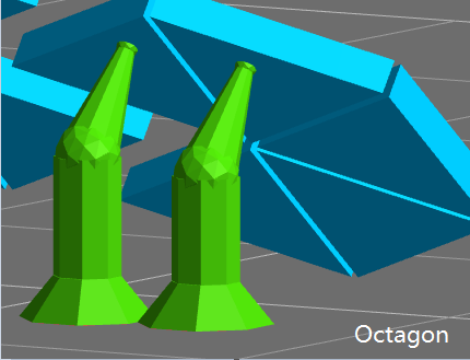
Shape
The software offers two shapes: Plus and Octagon

Head Type
The shape of the contact position between the support head and the model is a ball. The thickness of the connection between the support head and the ball differs with the setting of Head Type(50%~100%).

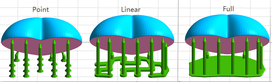
Base Type
The software offers three base types: Point, Linear and Full.
Base Thickness
The range of the base thickness is 0.5-2mm.
 TIP: In the automatic
support mode, the "Generate" and "Delete" buttons are only
available after the model is selected.
TIP: In the automatic
support mode, the "Generate" and "Delete" buttons are only
available after the model is selected.
Manual Edit
Click
the "Edit" button on the automatic support interface to enter the
manual editing. In this mode, users can add, modify and delete supports.

Add Supports
- Move
the mouse to the model, and if the green ball is marked at the mouse position,
it means that the normal vector of the position is down and support can be
added. Click the left mouse button to complete the new support work. If a red
ball is marked at the mouse position, it means that the normal vector of the
position is upward and no support is needed.
- When
you move the mouse, a white line will be displayed on the model. The white line
is a contour line, which means all the points on the white line have the same z
value. The white line can be used to easily find the floating point.
Select Supports
Mouse
click and box selection are available to select the support.
Modify Supports
- Click
on the support head and drag it to the target position on the model and then
release, the position of the support head will be modified.
- Left-click
on the support base and drag it to the target position on the platform to
release, the position of the support base will be modified.
- Select
one or more supports, modify the support diameter, support head length and
touch point size etc. The related properties of the model will be updated in
real time.
Delete Supports
- Press
the "Delete" button to remove the selected support.
- Click
"Remove All", all the supports will be removed.